The OV7670 is a low cost image sensor + DSP that can operate at a maximum of 30 fps and 640 x 480 ("VGA") resolutions, equivalent to 0.3 Megapixels. The captured image can be pre-processed by the DSP before sending it out. This preprocessing can be configured via the Serial Camera Control Bus (SCCB). You can see the full datasheet here.
There are many camera modules, that come with standard 0.1" spaced headers, in eBay with prices under $10. I'll be using the one shown below, it comes WITHOUT a FIFO buffer.

HARDWARE
The camera module comes with a 9x2 header, the pin diagram is shown below:
| VDD | GND |
| SDIOC | SDIOD |
| VSYNC | HREF |
| PCLK | XCLK |
| D7 | D6 |
| D5 | D4 |
| D3 | D2 |
| D1 | D0 |
| RESET | PWDN |
Now, I'll cover the meaning of these pins.
| Pin | Type | Description |
|---|---|---|
| VDD** | Supply | Power supply |
| GND | Supply | Ground level |
| SDIOC | Input | SCCB clock |
| SDIOD | Input/Output | SCCB data |
| VSYNC | Output | Vertical synchronization |
| HREF | Output | Horizontal synchronization |
| PCLK | Output | Pixel clock |
| XCLK | Input | System clock |
| D0-D7 | Output | Video parallel output |
| RESET | Input | Reset (Active low) |
| PWDN | Input | Power down (Active high) |
**A note about supply voltage and I/O voltage.
As stated in the datasheet:
- VDDA can range from 2.45V to 3.00V.
- VDDC can range from 1.62V to 1.98V.
- VDDIO can range from 1.7V to 3.00V.
You can (hopefully) see here (sorry, it's buried among other files) the schematic of the model I'm using in this post. As you can see U1 and U2 are LDO regulators, one is a 2.8V regulator for VDDA and VDDIO and the other is a 1.8V regulator for VDDC. The actual regulator that gets soldered on the module seems to vary between modules.
In conclusion, for the same model I'm using:
- You can safely supply 3.3V (3.0V - 3.6V) to the OV7670 VDD. (I used this configuration)
- You can safely use a maximum of 3.0V for the I/O pins. However the module I/O pins will work at 2.8V.
- A 5V supply for the OV7670 VDD might work (try at your own risk), it depends on the maximum input voltage of the LDO regulators your module has.
- You can use 3.3V on the I/O pins, the internal I/O protection diodes will clamp the I/O voltage to 2.8V. However, this may degrade the OV7670 faster and/or cause more power loss. (I used this configuration)
STRUCTURE OF AN IMAGE
Before going into the signaling, it's necessary to understand how video and images are representend in digital format.
A video is a succession of frames, a frame is a still image taken at an instant of time. A frame is compromised of lines, and a line is compromised of pixels. A pixel is the smallest part of a digital image, and it looks like a colored dot.
| P0 | P1 | P2 | P3 | P4 | |
| L0 | |||||
| L1 | |||||
| L2 | |||||
| L3 | |||||
| L4 |
A 5x5 image
For example, the image above has 5 lines, and each line has 5 pixels. This means the image has a resolution of 5x5 pixels. This image is monochrome, there are also color image. This color can be encoded in various formats, in the next section we'll cover the most relevant formats for the OV7670.
PIXEL FORMATS
Monochrome
In monochromes images, each pixel is stored as 8 bits, representing gray scale levels from 0 to 255. Where 0 is black, 255 is white and the intermediate values are grays.
RGB
Is a fact that any color can be decomposed in red, green and blue light at different intensities. This approach is known as the RGB color model. Using this model, each pixel must be stored as three intensities of these red, green and blue lights.

RGB color model. Image from wikipedia.
The most common format is RGB888, in this format each pixel is stored in 24 bits, the red, green and blue channels are stored in 8 bits each. This means that the intensity of each light can go from 0 to 255, where 0 is the absence of light, and 255 is the maximum intensity.
The formats used by the OV7670 are the RGB565, RGB555 and RGB444. The difference with the RGB888 format, is the number of bits assigned to each channel. For example, in the RGB565 format, the red channel is stored as 5 bits, the green channel as 6 bits and the blue channel as 5 bits. These formats take less memory when stored but in exchange sacrifice the number of colors available.
YCbCr
YCbCr is a format in which a RGB color can be encoded. The Y or luminance component is the amount of white light of a color, and the Cb and Cr are the chroma components, which respectly encode the blue and red levels relative to the luminance component.
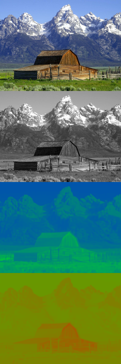
Decomposition of an image into its Y, Cb and Cr components. Image from wikipedia.
As you can see the Y channel encodes the gray scale levels of the image. Therefore, the easiest way to get a monochrome image from the OV7670 is to extract the Y channel of the YCbCr format.
As the RGB format, the YCbCr also stores each channel as 8 bits (from 0 to 255) and we can convert from YCbCr to RGB using the following expression.
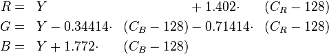
The OV7670 uses the YCbCr422 format, this format is stored as follows:
| Byte 0 | Byte 1 | Byte 2 | Byte 3 | |
| Word 0 |
Cb0
|
Y0
|
Cr0
|
Y1
|
| Word 1 |
Cb2
|
Y2
|
Cr2
|
Y3
|
| Word 2 |
Cb4
|
Y4
|
Cr4
|
Y5
|
Data stored as words (4 bytes)
Or equivalently, the data arrives in the following order:
N
|
Byte
|
1st
|
Cb0
|
2nd
|
Y0
|
3rd
|
Cr0
|
4th
|
Y1
|
5th
|
Cb2
|
6th
|
Y2
|
7th
|
Cr2
|
8th
|
Y3
|
...
|
...
|
And the actual pixels are the following:
| Pixel 0 | Y0 Cb0 Cr0 |
| Pixel 1 | Y1 Cb0 Cr0 |
| Pixel 2 | Y2 Cb2 Cr2 |
| Pixel 3 | Y3 Cb2 Cr2 |
| Pixel 4 | Y4 Cb4 Cr4 |
| Pixel 5 | Y5 Cb4 Cr4 |
Notice each pixel is 3 byte long (e.g. Y0, Cb0 and Cr0), as in the RGB format. But, in the YCbCr422 format, the Cb and Cr channels are shared between two consecutive pixels (e.g. pixels 0 and 1 share Cb0 and Cr0). Therefore two pixels are "compressed" into 4 bytes or 32 bits, this means that in average each pixel is stored as 2 bytes or 16 bits. From the example above, 3 words (12 bytes) store 6 pixels.
The extra advantage of YCbCr is that the Y channel is the grayscale image, whereas in RGB you'll need to average the 3 channels to get the grayscale image.
The extra advantage of YCbCr is that the Y channel is the grayscale image, whereas in RGB you'll need to average the 3 channels to get the grayscale image.
SIGNALING
The OV7670 sends the data in a parallel synchronous format. First of all, to get any data out of the OV7670, is necessary to supply a clock signal on the XCLK pin. According to the datasheet, this clock must have a frequency between 10 and 48 MHz. However, I have successfully used a 8 MHz clock with some configuration via the SCCB.
If you are using a microcontroller that has clock output, you can use that to clock the OV7670, these can generally output their inner system clock prescaled by some factor. If your microcontroller doesn't have clock output capability, but you're using an external crystal, then you can connect the OSC_OUT pin to the OV7670.
After a clock signal has been applied to the XCLK pin, the OV7670 will start driving its VSYNC, HREF and D0-D7 pins. Let's take a look at these signals.

Horizontal Synchronization
First thing to notice, the D0-D7 must be sampled at the rising edge of the PCLK signal. Number two, D0-D7 must be sampled only when HREF is high. Also, the rising edge of HREF signals the start of a line, and the falling edge of HREF signals the end of the line.
All these bytes sampled when HREF was high, correspond to the pixels in one line. Note that one byte is not a pixel, it depends on the format chosen. By default, the format is YCbCr422, this means that in average two bytes correspond to a pixel.

VGA timing
The image above shows the signals for a "VGA" (640 x 480) frame. During HSYNC high state, we must capture 640 pixels, equivalent to a line. The 480 lines, equivalent to a frame, are captured during the low state of VSYNC. This means that the falling edge of VSYNC signals the start of a frame, and its rising edge signals the end of a frame.
That covers all the process of obtaining one frame, the remaining question is how fast are frames sent. By default, the PCLK will have the same frequency of XCLK, however prescalers and PPLs can be configured using the SCCB, to produce a PCLK of different frequency.
A PCLK of 24 MHz will produce 30 fps, a PCLK of 12 MHz will produce 15 fps and so on. All this is independent of the format of the image (VGA, CIF, QCIF, etc).
SCCB (Serial Camera Control Bus)
What makes the OV7670 so versatile is its inner DSP, that can pre-process the image before its sent. This DSP can be accessed via a SCCB interface. This SCCB protocol is very similar to the I2C protocol. You can see the SCCB specification here.
I couldn't get my STM32 microcontroller's I2C module to work with the OV7670's SCCB interface, so I implemented a bit bang version of the SCCB specification. This implementation is my peripheral library libstm32pp.
After making sure the SCCB is working, we can tweak the OV7670.
Changing the FPS
To change the frames per second (fps), we need to change the frequency of PCLK. And for that we need to modify the following registers via the SCCB.
| Register | Address | Default | Description | ||||
|---|---|---|---|---|---|---|---|
| CLKRC | 0x11 | 0x80 |
|
||||
| DBLV | 0x6B | 0x0A |
|
Now that you know the involved registers, the process is straightforward. For example, say we have a 8 MHz input clock and we want a 24 MHz PCLK. The only possible configuration is prescaler by 2, and PLL x6.
- CLKRC Bit[6] must be 0, to enable prescaler.
- CLKRC Bit[0-5] must be 1, to enable prescaler by 2.
- DBLV Bit[7-6] must be 10, to enable PLL x6
Pseudocode:
Changing the frame format/resolution
The OV7670 can use various frame formats:
- VGA (640 x 480)
- QVGA (320 x 240)
- CIF (352 x 240)
- QCIF (176 x 144)
- Manual scaling
By default, the OV7670 uses the VGA format, if you want to do image processing on a microcontroller with the OV7670 output, this may be way too much data, and you might want the QCIF format instead. To change the format we need to modify the following registers.
| Register | Address | Default | Description | ||||||||||||
|---|---|---|---|---|---|---|---|---|---|---|---|---|---|---|---|
| COM3 | 0x0C | 0x00 |
|
||||||||||||
| COM7 | 0x12 | 0x00 |
|
Example, say we want to use the QCIF format, we'll need to enable the scaling, and select the QCIF format.
- COM3 Bit[3] must be 1, to enable scaling
- COM7 Bit[3] must be 1, to use the QCIF format
Pseudocode:
I'll add more possible configurations as I explore other features.
MY RESULTS
I have tested my OV7670 module, with a STM32F4 microcontroller. This microcontroller comes with a Digital CaMera Interface (DCMI) and a Direct Memory Access (DMA) controller, these two can capture the frames without the intervention of the processor.
I used an XCLK of 8 MHz, but configured the OV7670 to output a PCLK of 24 MHz, this means I was capturing 30 fps. I used the QCIF format, however I was receiving 174 x 144 pixels instead of 176 x 144. Color format was the default YCbCr422. One of every six frames was sent to a PC using a UART communication at 3 Mbps.
On the PC side, I received the frames using a modded version of qSerialTerm, only the Y channel (gray scale version) of the incoming frames was used. The result is shown in the following image.

A ninja star servo horn captured by the OV7670 camera module.
Now you can use qSerialTerm to visualize images streamed through the Serial Port. Check this post for more info.
TROUBLESHOOTING
SCCB:
- Make sure the SCCB is working properly, the OV7670 will answer with an ACK, after it has been address properly.
- The 7 bit SCCB/I2C address is 0x21, this translates to 0x42 for write address and 0x43 for read address.
- For debugging purposes, try reading some registers and check that they contain their default values. e.g. reading the 0x01 register should return 0x80.
- Always read a register first, modify the desired bits and then write it back to the OV7670.
Image sensor
- Check wiring, pin configuration and clock configuration.
- Start only grabbing a snapshot (only one frame), this is from VSYNC falling edge to VSYNC rising edge. Repeat this procedure multiple times, and make sure the number of bytes per snapshot, is constant.
- Cover the camera lens, and verify that the snapshot have the following information (in bytes): 128 0 128 0 128 0 128 0 ... i.e. every even byte should be 128 and every odd byte should be 0. This correspond to a pitch black image.
- If the two previous experiments fail, your uC might be too slow to grab the OV7670 stream, either increase its clock speed or get a faster uC. If you are using a DMA controller, then give it high priority, clock it as fast as possible and/or dedicate it to this task.
- If you are visualizing the grabbed snapshot in a PC, for starters only use the luminance (Y) channel, i.e. only use the even bytes of the snapshot. On the PC, assign R = G = B = Y for each pixel.
- At this point, all the electrical/software part should be working. The only remaining issue is the camera focus (distance from the camera lens to the image sensor), you will have to vary the camera focus by trial and error until you get a clear image.

Varying the camera focus

UPDATE: Check this post about 3 demos that involve the STM32F4, the OV7670 and qSerialTerm. Full code available.

qSerialTerm displaying a frame sent by the STM32F4 and was captured by the OV7670


