First of all, I want to thank the OpenOCD Project for its latest release of OpenOCD. Thanks to this release, its possible to get a working development environment for the STM32F4DISCOVERY relatively fast.
This Development Environment can also be used for other STM32 / Cortex M microcontrollers and development boards. I have tested this Development Environment with the STM32VLDISCOVERY, STM32F4DISCOVERY and F4Dev.
For now this post is Ubuntu specific. Setting the Development Enviroment on other platforms should be fairly similar.
Dependency: GCC
You need a GCC (GNU Compiler Collection) for ARM Cortex processors: You can use the official GCC build (4.6.2) or the Mentor Graphics (former Code Sourcery) GCC build (4.5.2) (Do not use the CodeSourcery GCC, the latest library code requires GCC version 4.6 or later).
I'll cover how to install the official GCC build, since it's a newer version.
Windows
Grab the installer, follow the installation steps, and check the "Add path to environment variable" checkbox just before finishing the installation.
Linux
Grab the Linux installation tarball.
Untar the tarball and that's it, no need to launch a installer.
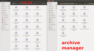
Note: Ubuntu 12.10 users, use the command line tar instead of the GUI archive manager. The latter will result in missing binaries in the bin folder. See image below.


That's it for the GCC dependency.


Grab the zip from here. Unzip the file. Copy the uncompressed folder in your C drive.
Append ";C:\openocd-0.6.1\bin" or ";C:\openocd-0.6.1\bin-x64" to your PATH variable. See this post if you don't know how to edit the PATH environment variable.


** Windows: Edit the (Eclipse > Project > Properties > C/C++ Build > Build command) to "mingw32-make" or whatever make you are using.


And...

Grab the libusb-win32 library. Unzip the downloaded zip archive in your C drive. Enter in the uncompressed folder, then enter into the bin folder and execute the inf-wizard.
Follow the instructions, select the right device ("Single RS232-HS" or similar) from the list. Save the .inf file anywhere and finally select Install Now.
If you are using or planning to use the STM32VLDISCOVERY, then you need these additional steps:
Inside that new file, insert the following text:


NOTE: 84 MHz and latency one SHOULD be equivalent to 42 MHz, since the uC will execute one instruction and wait one cycle before executing the next instruction. However, when you take in consideration that instructions can take more than one cycle (e.g. FPU operations) and program jumps (due to functions and interrupts), calculating the "real" operating frequency gets really hard.
My recommendation: Stick to 42 MHz max with zero latency while developing your application. After everything works fine, try increasing the clock and try different values for the latency until you get something stable. Then check if you are actually getting better performance on the AHB bus peripherals.


Note: Ubuntu 12.10 users, use the command line tar instead of the GUI archive manager. The latter will result in missing binaries in the bin folder. See image below.

Do not use the GUI archive manager
Use the following command instead:
tar jxf gcc-arm-none-eabi-4_6-2012q2-20120614.tar.bz2
Let's add the GCC binaries folder to the PATH environment variable, for easier use.
gedit $HOME/.profile
Append to this file the following lines:
Do a soft reboot to update the PATH variable.
The binaries should be accessible from the command line, let's check.
arm-none-eabi-gcc --version
You should see an output similar to the following lines:
If instead you get the following error and you are using a 64bit Ubuntu/Linux OS:
It means you are missing some 32 bit libraries. The easiest way to solve this is to install all the 32 bit libraries using the following command:
sudo apt-get install ia32-libs
Now test again the arm-none-eabi-gcc command and it should work.
That's it for the GCC dependency.
Dependency: Eclipse CDT
You'll need Eclipse C/C++ Development Tooling.
I recommend using Eclipse Indigo instead of Eclipse Juno, because there
is a bug with the content assist when using namespaces.
Grab the correct package from here. (If you still want to use the Juno version, get the package from here)
Untar / unzip the tarball / zip file, and you are done.
If you don't have Java installed, head to this link. Grab the correct installer (x86 or AMD64), then follow the installation steps.
After installing Java, Eclipse should work.
Windows
If you don't have Java installed, head to this link. Grab the correct installer (x86 or AMD64), then follow the installation steps.
After installing Java, Eclipse should work.
Dependency: GNU ARM Plugin
With this plugin, Eclipse will be able to detect the ARM GCC.
In Eclipse, go to (Help > Install New Software).
On this new window, click the add button, and insert the following text.
http://gnuarmeclipse.sourceforge.net/updates

Click OK and a component named "CDT GNU Cross Development Tools" will appear, check it, then click the Next button and following the installation instructions.

You'll be prompted to reset Eclipse, do so.
You're done with this plugin.
Dependency: Zylin Embedded CDT Plugin
This plugin is necessary to flash and debug within Eclipse.
In Eclipse, go to (Help > Install New Software).
On this new window, click the add button, and insert the following text.
http://opensource.zylin.com/zylincdt

Click OK and a component named "Zylin Embedded CDT" will appear, check it, then click the Next button and following the installation instructions.

You'll be prompted to reset Eclipse, do so.
You're done with this plugin.
Dependency: OpenOCD
With this software, your PC will be able to flash and debug STM32 targets via a USB <-> JTAG interface.
Windows
Grab the zip from here. Unzip the file. Copy the uncompressed folder in your C drive.
Append ";C:\openocd-0.6.1\bin" or ";C:\openocd-0.6.1\bin-x64" to your PATH variable. See this post if you don't know how to edit the PATH environment variable.
Linux
Grab the version 0.6.0 tarball from here.
Untar the tarball.
Use the following installation commands:
sudo apt-get install libftdi-dev
cd <path to the untared openocd tarball>
./configure --enable-ft2232_libftdi --enable-stlink
make
sudo make install
cd <path to the untared openocd tarball>
./configure --enable-ft2232_libftdi --enable-stlink
make
sudo make install
You're done with the OpenOCD installation.
If you don't have Git installed. Grab the installer from here. Follow the installations steps, but choose the "Run Git from the Windows Command Prompt" instead of the default option.
Windows doesn't come with a "make" tool by default. The easiest way to get "make" is downloading this MinGW (**). Then unzip the downloaded zip archive in your C drive.
(**) The trolltech ftp server has been shutdown, luckily ShaoLin has posted a mirror on his Google Drive, check his post for information on how to download MinGW.
And append ";C:\mingw\bin" to your PATH variable. See this post if you don't know how to edit the PATH environment variable.
Git (Windows)
If you don't have Git installed. Grab the installer from here. Follow the installations steps, but choose the "Run Git from the Windows Command Prompt" instead of the default option.
Make (Windows)
Windows doesn't come with a "make" tool by default. The easiest way to get "make" is downloading this MinGW (**). Then unzip the downloaded zip archive in your C drive.
(**) The trolltech ftp server has been shutdown, luckily ShaoLin has posted a mirror on his Google Drive, check his post for information on how to download MinGW.
And append ";C:\mingw\bin" to your PATH variable. See this post if you don't know how to edit the PATH environment variable.
The Eclipse Project Template
Grab the Eclipse project template I have developed: bareCortexM
cd # choose some directory
git clone https://github.com/JorgeAparicio/bareCortexM.git
git clone https://github.com/JorgeAparicio/bareCortexM.git
Importing the Eclipse Project
In Eclipse, go to (File > Import).
In this window, select (General > Existing Project into Workspace).
In this new window, click the Browse button next to the "Select root directory" box and select the bareCortexM folder.

In this project, go to the "src" folder and open the "main.cpp" file. You should see a single function named int main().
From the Eclipse menu select (Project > Properties).
In this windows, select the C/C++ Build.
Click the Manage Configuration button next to the Configuration combo box.
Select your platform and click the Set Active button. (By default the Linux platform is selected).

** Windows: Edit the (Eclipse > Project > Properties > C/C++ Build > Build command) to "mingw32-make" or whatever make you are using.
Now try building the project, if you correctly followed the previous steps the build should be successful.

Configuring the project for your target
Before flashing your target (in this case the STM32F4DISCOVERY) it's necessary to configure the project for your specific target.
Linker Script selection
The linker script contains the memory map of your target device.
In the Eclipse menu, go to (Project > Properties).
Now select C/C++ (Build > Settings).
Select (ARM Sourcery GCC C++ Linker > General).
Modify the file in the Script File text box, to match your target device.

You can see the list of supported devices in the linker folder.

OpenOCD interface/target configuration
You'll need to tell OpenOCD which interface and target you plan to use.
In the Eclipse menu, (Run > External Tools > External Tool Configurations).
In this new window, select (Program > OpenOCD).
On the Main tab, make sure the OpenOCD location is correct. Then modify the arguments as necessary.

The first argument to modify is the interface: "-f openocd/interface/<your interface>.cfg". You can see the list of supported interfaces in the (openocd > interface) folder.

The second argument to modify is the target: "-f openocd/target/<your target>.cfg". You can see the list of supported targets in the (openocd > target) folder.

GDB script selection
The GDB script contains the flash and debug information.
In the Eclipse menu, go to (Run > Debug Configurations).
In this new window, select (Zylin Embedded debug (Native) > Flash and Debug).
On the Debugger tab, you'll need to select an appropriate GDB script in the GDB command file text box.

You can see the list of supported devices in the gdb folder.

Configuration table
| Board | Linker Script (.ld) |
Interface (.cfg) |
Target (.cfg) |
GDB Script (.script) |
|---|---|---|---|---|
| STM32VLDISCOVERY⁽¹⁾ | stm32f100rb | stlink-v1 | stm32f1x_stlink | stm32vldiscovery |
| STM32F4DISCOVERY | stm32f407vg | stlink-v2 | stm32f4x_stlink | stm32f407vg⁽²⁾ |
| F4Dev | stm32f407ve | ujtag | stm32f4x | stm32f407ve⁽²⁾ |
⁽¹⁾: Flash protection must be disabled (probably using other JTAG dongle) before using this configuration.
⁽²⁾: You can use other scripts like: stm32f4_16kb, stm32f4_32kb, etc. for faster flashing.
The first program
Let's flash your first program into the STM32F4DISCOVERY.
Copy the following code in the main.cpp source file.
Build the program, and then click the OpenOCD action in the External Tool menu (The green play + red toolbox icon) or go to (Menu > Run > External Tools > OpenOCD).
And...

What the...?
If you are a Linux user, you'll probably bump into that error. You'll need to give permission to your interface device, this way a non-rooted Eclipse will be able to flash and debug the target device.
USB Permissions/Drivers
Windows (for FTDI devices)
Grab the libusb-win32 library. Unzip the downloaded zip archive in your C drive. Enter in the uncompressed folder, then enter into the bin folder and execute the inf-wizard.
Follow the instructions, select the right device ("Single RS232-HS" or similar) from the list. Save the .inf file anywhere and finally select Install Now.
Linux
To grant permission to your interface device you'll have create a file using the following command.
gksudo gedit /etc/udev/rules.d/33-openocd.rules
(You can choose any other number, instead of 33)
In this new file you'll need to add the following text:
This will give permission to all the FTDI based JTAG-dongles and to the ST-LINK v2 JTAG interface present in the STM32F4DISCOVERY.
If you are using or planning to use the STM32VLDISCOVERY, then you need these additional steps:
gksudo gedit /etc/modprobe.d/stlink_v1.conf
Inside that new file, insert the following text:
NOTE: Currently, ST-LINK v1 via OpenOCD can't modify the target device flash protection. This means, that if your STM32VLDISCOVERY has its flash protection enabled, you won't be able to flash it. On the other hand, if you manage to disable the flash protection using other JTAG dongle, then you'll be able to use the ST-LINK v1 connection. OpenOCD will probably provide better support for ST-LINK v1 in the future.
A reboot is necessary to update the last changes.
A reboot is necessary to update the last changes.
After that, the permission problem should be fixed.
Back to the first program
As before, launch OpenOCD. You should get the following output this time.

That X breakpoints and Y watchpoints is the equivalent of success. Now that you have established a link between your PC and the microcontroller, you can begin the flash and debug session.
Click the Flash and Debug action in the Debug menu (the green bug icon). The flashing process will start, and it will take a while... around 20s (if you using a device with big flash memory, otherwise it's faster).
NOTE: Actually flashing your program is quite fast, since is probably around 200-300 bytes, what takes so much time is erasing the old memory. The whole flash memory get erased before writing the new program. You can achieve faster flashing times if you only "use" a fraction of the memory, when using scripts like stm32f4_16kb, stm32f4_32kb, etc.
After the flashing is over, you'll go into the debug session. You'll be prompted if you want to change to the Debug perspective, answer yes.
Debugging 101
Let's do some debugging now. First, let's examine this new perspective.

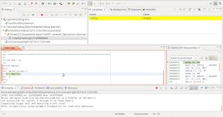
In the top left window, you'll see Debug window. Inside this window you'll see Thread 1, this is the program that's currently running, notice that it says suspended, this means that the ARM core is halted. Also, below Thread 1 you can see the stack of functions called, right now it says the program is at 0x00000000, this is because the JTAG interface hasn't asked for information yet.
Also in the debug window you can see some buttons, that I have labelled from 1 to 7. Now I'll cover what they do:
| N | Button | Description |
|---|---|---|
| 1 | Resume (F8) | Leaves the suspended status. |
| 2 | Suspend | Halts the program execution. |
| 3 | Terminate (Ctrl + F2) | Finishes the program. |
| 4 | Step into (F5) | Goes (if possible) into the current subroutine. |
| 5 | Step over (F6) | Executes the current line of code and moves onto the next. |
| 6 | Step return (F7) | Leaves the current subroutine. |
| 7 | Instruction Stepping Mode | Enables/disables the instruction stepping mode. (Disabled by default) |
Ok, now hit the Resume button and then click the Suspend button. You'll end in a state similar to the following image.

You can see that the middle left window changed, and now is showing the main.cpp file. Also, there is a highlighted line, this is where the halted program currently is. You can also see the disassembly of the current program in the middle right window, if you can't, then you can enable the disassembly from (Menu > Window > Show View > Disassembly).
NOTE: Read this note if your program ends in the defaultExceptionHandler() function instead.
This is a common error (bug?) that appears when you are using ST-LINK
connections (in the STM32VLDISCOVERY or STM32F4DISCOVERY). In this case, terminate (red square button) the debug session and the OpenOCD connection. And then do the build > launch OpenOCD > start debug session process again.
Let's watch some variables now, select the Variables tab of the top right window and right click the empty space, then click on Add Global Variables.

Check the foo variable and then click OK. You can now watch the value of foo. Try resuming the program for a while and then suspend it again. You should see a noticeable increment in the value of foo.

Now, let's see how breakpoints work. Right click the line 27 (it doesn't matter if you can't see the line number) and select Toggle Breakpoint. Now hit the Resume button.

The program will stop as soon as it reaches the breakpoint, you'll notice that foo's value increased in one.
Let's terminate the program (Flash and Debug) and then terminate the OpenOCD session and jump into something more interesting.
Blinking a LED
bareCortexM is a barebone project template, you'll need a peripheral library to do more than just numerical operations. This is where libstm32pp comes in.
Adding the libstm32pp library to the project
Let's place the libstm32pp project inside the bareCortexM project.
cd <path to bareCortexM>
git clone https://github.com/JorgeAparicio/libstm32pp.git
git clone https://github.com/JorgeAparicio/libstm32pp.git
Go back to eclipse, and right click the project name (bareCortexM) and select the Refresh action. You should see the libstm32pp folder inside the project.

Now, you'll need to add the library to the include path.
In Eclipse menu, go to (Project > Properties).
Go to (C/C++ General > Paths and Symbol).
In the Includes tab, select the GNU C++ in languages and then click the Add button.
In this new window, click the Workspace button and select the (libstm32pp > include) folder.

Configuring the library
You'll need to configure the library to match your target, head to the (libstm32pp > include) folder and open the device_select.hpp. There you can select your target's family by commenting and uncommenting the defines in that file.

Using the library
Go into the (libstm32pp > demo) folder and open the gpio_pin.hpp file. Copy the content to your main.cpp file. You can change the LED pin from PA0 to any other pin you wish. For the STM32F4DISCOVERY you can select PD12, PD13, PD14 or PD15 to use the user LEDs available in the board. For the STM32VLDISCOVERY use the PC8 and PC9 instead.
After that, build, launch OpenOCD and start the debugging session.


Configuring the Clock
If you want to configure your device clock head to the (libstm32pp
> include) folder and open the clock.hpp file. As in device_select.hpp, by
commenting / uncommenting defines you can configure the clock to fit
your needs.

The clock will be configured when you call the function clk::initialize(). You should call this function as earlier as possible in your main function. If you are using any of the external crystals/oscillators (HSE or LSE) then you'll need to define the functions: clk::hseFailureHandler and clk::lseFailureHandler. These functions will be called in case the external oscillators doesn't stabilize in some time as dictated by HSE_TIMEOUT and LSE_TIMEOUT.

The STM32 microcontrollers use various buses (AHB, APB) to move data between the processor and the peripherals. These buses define the operating frequency of various peripherals and these buses can be clocked at different frequencies. All this configuration is carried in the clock.hpp file, you can check the final frequencies using the cPrint statement:

The cPrints statement prints its argument as an error. In the above image I used the cPrint statement to print the value of clk::AHB which the working AHB frequency. You can use cPrint to print other compile time known values, as cPrint creates an error, be sure to remove it or comment it after using it.
NOTE: As far as I know, the STM32F4 devices from the revision "A" can't use the ART accelerator (see the errata sheet here), for these devices the LATENCY parameter is important when configuring the clock. From my observations the following latencies work well:
| Clock Frequency (AHB) | LATENCY | Comment |
|---|---|---|
| Up to 42 MHz | Zero | Solid Rock Stable. |
| From 42 Mhz to 84 MHz | One | Seems stable. |
| 168 MHz | Three | Some WTFs when using interrupts and enabling optimization. |
NOTE: 84 MHz and latency one SHOULD be equivalent to 42 MHz, since the uC will execute one instruction and wait one cycle before executing the next instruction. However, when you take in consideration that instructions can take more than one cycle (e.g. FPU operations) and program jumps (due to functions and interrupts), calculating the "real" operating frequency gets really hard.
My recommendation: Stick to 42 MHz max with zero latency while developing your application. After everything works fine, try increasing the clock and try different values for the latency until you get something stable. Then check if you are actually getting better performance on the AHB bus peripherals.
Handling interrupts
The most important feature in every microcontroller are the interrupts. With these interrupts the microcontroller can handle various internal/external events as they come by.
To enable interrupts you'll need to map the interrupt handlers in memory. I've already done this job, so you only need to include "interrupt_cpp.hpp" file in the "interrupts.cpp" source file (this is in the src folder).

Let's try a demo now, go to the (libstm32pp > demo) folder and open the tim_blink_led.hpp file, or if you are using a STM32F4DISCOVERY go to (libstm32pp > demo > f4discovery) folder and open the led_wheel.hpp file. Copy the content of the file to main.cpp.
In the tim_blink_led demo you might want to change the LED from PA0 to some other pin. In either demo you can change the LED blink frequency by changing the configurePeriodicInterrupt function argument.
Build, launch OpenOCD and start the debugging session.

LED Wheel demo @ 16Hz
New, delete and printf
Since you're developing in C++, it's possible to use the operators new, delete and input/output functions like printf. You can also use the cout function, but it takes too much flash memory, so I'll recommend using printf instead.
To enable these functions, you'll need to define the system calls. The system calls are hardware dependant standard functions like read, write, close, start, exit, sbrk, etc. libstm32pp provides a minimal implementation, which is enough to use the new, delete and printf functions.
To enable the system calls, you'll need to include the "system_call_cpp.hpp" file in the "system_call.cpp" source file (located in the src folder).

Also you'll need to enable the startup libraries.
In Eclipse, go to (Menu > Project > Properties).
Go to (C/C++ Build > Settings).
In the Tool Settings tab, go to (ARM Sourcery GCC C++ Linker > General).
Uncheck the "No startup or default libraries".

new demo
Let's do a quick demo about the new operator. Write in your main.cpp source file the following code:
Build, run OpenOCD and start a debugging session as usual.

The first thing you'll notice is that this small program takes around 90KB of flash. That's the price to pay for using dynamically allocated memory. If you watch the foo variable after running the program for some time, you'll notice that the pointer has a value around 0x20000000, this is the address that the new operator assigned it and also you can see the value stored in that address, which would be the first element of the array.
printf demo
There is a printf demo in the (libstm32pp > demo) folder. You can use printf with any of the 6 UART modules, which needs to be specified in the system_call.hpp file (this is in the (libstm32pp > include) folder). You'll also need a USB <-> UART converter to get the UART output into your PC. In your PC, you'll need a serial port terminal emulator like minicom or qSerialTerm.
Optimization
Finally, let's cover how to do optimization.
In eclipse, go to (Menu > Project > Properties).
Go to (C/C++ Build > Settings).
In the Tool Settings tab, go to (ARM GCC C++ Compiler > Optimization).
Select in the Optimization Level, the option that fits your need.

My recommendation: When developing an application, I recommend working with the optimization turned off and turning it on after you have finished developing. This is because the optimization will complicate the debugging process, as the compiler will optimize out some variables and also some breakpoints might misbehave.
Feedback is welcome
There are many other demos inside the (libstm32pp > demo) folder. Please check them and inform me if you find any bug. I'll appreciate your feedback. Thanks.


