|  |
Yup, that mess of wires actually works.
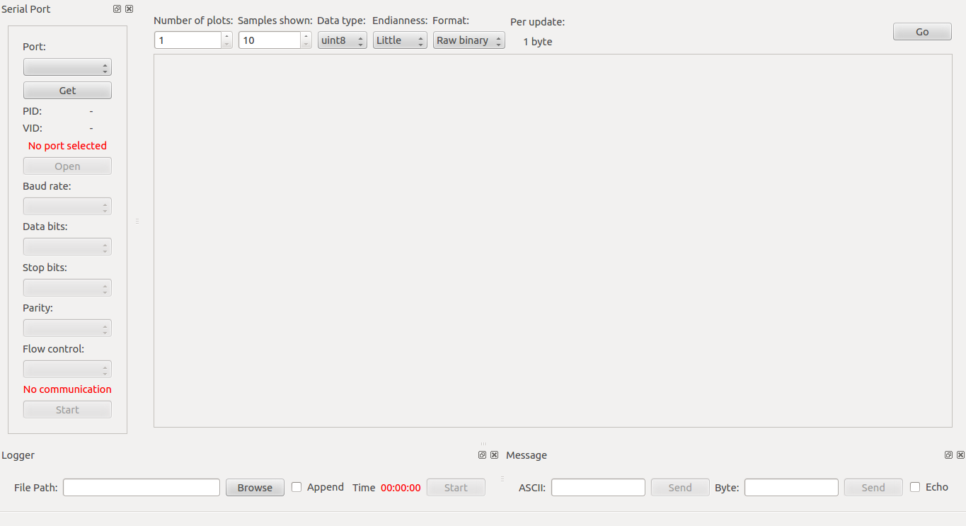
In this post I'll cover 3 basic demo programs for the STM32F4 to interface the OV7670. Additionally, I've use qSerialTerm to receive data from the uC and display it in a human readable form.
I assume you know how the OV7670 works and have some knowledge about common peripherals found in uC (GPIO, USART, DMA, etc).
The board used in this demo was the custom development board: F4Dev. The STM32F4DISCOVERY wasn't used and can't be used because the Digital Camera Interface (DCMI) peripheral pins are not fully available in that development board.
I've used bareCortexM, an Eclipse based IDE, and libstm32pp, a template peripheral library, to develop these demos for the STM32F4.
The following configuration applies to all the demos:
- The STM32F4 operated at 42 MHz, the system clock, the AHB clock, the APB1 clock and the APB2 clock, all of them operated at this frequency.
- This 42 MHz frequency was obtained from the uC High Speed Internal (HSI) oscillator, which runs at 16 MHz, after scaling up the frequency using the uC internal PLL.
- The MCO1 pin was configured to output the HSI clock (16 MHz) and this output was used to drive the OV7670 XCLK.
Demo 1: Scanning the SCCB bus (Code)
In this first demo, the STM32F4 will interface the OV7670 using a bit bang implementation of the SCCB protocol.
The uC will wait until the letter 'S' is received on the USART1 interface. Upon receiving this signal, the uC will read all the internal registers of the OV7670 using the SCCB interface.
After scanning all the OV7670 registers. The uC will report the address and values of the registers via the USART1 in a human readable format.
 |  |
Default values of the internal registers of the OV7670
You can find the log file of the uC output here.
Under the hood details: The formatting was done using the printf function.
Demo 2: Reading a frame and visualizing the data in hex format (Code)
In this second demo, the STM32F4 will interface the OV7670 using the Digital Camera Module Interface (DCMI) to grab a frame from the OV7670 and then display the data in hexadecimal format.
The uC will wait until the letter 'S' is received on the USART1 interface. Upon receiving this signal, the uC will use the DCMI in single shot mode to grab one frame from the OV7670.
After capturing the frame, the uC will send all the data via the USART1 interface in a human readable hexadecimal format.
 |  |
Frame taken in a pitch black environment. Data in hex format.
You can get the full log file here.
Under the hood details: The DCMI peripheral works hand to hand with the DMA peripheral. The data that is captured by the DCMI is moved by the DMA to a predetermined memory address without intervention of the uP. The formatting was done using the printf function.
Demo 3: Reading a frame and visualizing the data as an image (Code)
The last demo is pretty similar to the second demo. The difference is that the uC reports the frame data in binary form. On the PC side, this binary data is parsed and displayed in qSerialTerm.
 |  |
Frames captured by the OV7670. Left: A electrical tape. Right: Pitch black image.
Under the hood details: After capturing the frame, the data was sent through the USART interface using the DMA peripheral.
That's it. You have access to my full code, both the STM32F4 firmware and the qSerialTerm are fully available to you. I hope this information will help you in projects that involve the OV7670.