In this post I'll cover how to simulate a multibody system (a "robotic arm") using the Simmechanics toolbox in Simulink, which is an extension of Matlab.
We'll build a simple "robotic arm" with 3 degree of freedom (DOF). Each DOF will be rotational and will be actuated by a "servomotor", which will be implemented as a closed loop PID position controller.

We won't build this one in this tutorial, as it requires too many steps. We'll build something simple to illustrate the method, then you can build this one on your own.
I won't give you the final .mdl file, instead I'll give you all the necessary steps, so you can learn by doing.
OK, let's go hands on!
The environment
First, let's explore the environment. Launch Matlab and then open Simulink, either by using the command simulink in the command line or by clicking the simulink icon in the toolbar.

Launching Simulink
The Simulink Library Browser will open, here you'll find a bunch of building blocks that can be used to assemble Simulink models. We'll be using the first generation or legacy Simmechanics blocks located under the Simscape library. After you find these blocks, create a new model by clicking the blank page icon.

Starting a new simulink model
A new blank window, name untitled, will appear. This is the simulink model, we can drop blocks here to build models, which can later be simulated. You'll notice there is a play button which is disabled, that button starts the simulation.
A blank Simulink model...
Let's start by dropping a Ground block in the model, I'll explain what it does soon enough. You can find the Ground block inside the Bodies category of the Simmechanics blocks. Drag the Ground block and drop it inside the white are of the Simulink model.

Gaining ground on Simulink.
The coordinate system
Simulink uses an XYZ Cartesian coordinate system to describe the position of the bodies and Euler angles to describe the orientation of the bodies. Let's take a look at the global coordinate system (CS) by starting a simulation.
First, head to the menu > Simulation > Configuration Parameters. On the new window, go under the Simmechanics 1G (or simply Simmechanics) category and enable the animation by checking the "Show animation during simulation" checkbox.

Enabling animation.
Click the apply button and close the window. Now hit the play button (Start simulation). In the new window that pops out, select the isometric view as shown in the next image.

The Coordinate System and an empty animation.
You just did your first animation, there is nothing in it but the global coordinate system. Now, notice that the Y axis is pointing up, this is also the axis where the gravity acts (in the -Y direction). Some people, me included, tend to draw the Z axis pointing up and use the -Z direction for the gravity. Simulink doesn't follow this Z convention, so be careful.
The multibody paradigm: bodies and joints
As the name implies, multibody systems are composed of various bodies, where a body can be any rigid piece of matter. Two bodies are connected by joints, these joints allow one or more DOF (i.e. relative movement) between the bodies.
Most multibody system can be described as "open chains", i.e. as a series of bodies and joints that form a line or a tree, but not a loop. In Simmechanics, these chains must start with the Ground block, the Ground is a body with infinite mass and moment of inertia. Let's explore the Ground block by double-clicking it.

Ground block parameters
The Ground block is located at some [x, y, z] global position. This point is where other bodies will make a joint to the Ground. Leave the default [0, 0, 0] position.
The simplest example: A pendulum
To better understand the joint and body system, let's start by building a simple pendulum system. Add a revolute block, located under the Joints category, and a body block, located under the Bodies category, to the Simulink model. Then, link these block by click dragging a line from one block to another, the final diagram should look like the following image.
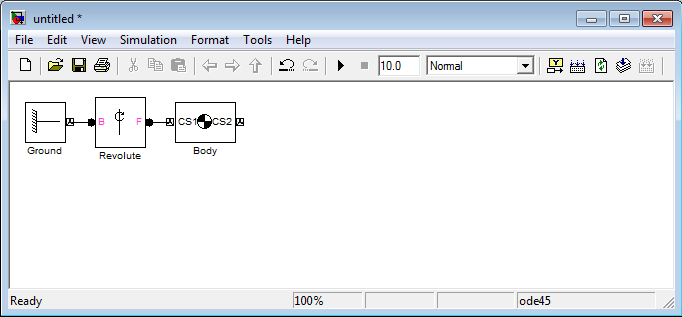
Pendulum diagram.
Let's add parameters to the Body block. The Body will be a 1 meter zero-thickness bar with a mass of 1 Kg. Double click the Body block and modify the parameters to match the following image.

Bar parameters.
Click apply and close this window. Now change the simulation time to 2 (seconds) and hit the play button. On the new window, click the "Enable automatic expanding fit" button to take a better view at the pendulum movement.

Simulating a pendulum.
Analyzing the pendulum
Now that we have a visual, I'll proceed to explain how the Coordinate Systems (CS) works.

The pendulum CSs.
Let's look at the big picture, we have the Ground, which is our reference point for this kinematic chain and is located at [0, 0, 0]. Next we have a Body (the bar) with two CSs (Coordinate Systems), each CS is attached to one particular point of the body as you can see.
The Ground and the Body are connected by a Revolute block, which is a joint. A joint is a relationship between two CS, one CS for each intervening body. The joint add restrictions between these two CS, because in 3D space an unrestricted CS has 6 DoF with respect to another CS. In our example the Revolute joint only allows 1 rotational DoF in the Z axis direction ([0, 0, 1]). This means that CS1 can't translate with respect to the Ground, i.e. it will remain at the global position [0, 0, 0], and can only rotate around the global Z axis.
Let's now analyze the Body parameters. We have three Coordinate Systems: CS1, CS2 and CG. The CG is the center of gravity and the other two CS are for reference/positioning. To specify the position of any CS we need:
- A first CS, which I'll call the rCS: reference Coordinate System
- A second CS, which I'll call the oCS: orientation Coordinate System
- A [x, y, z] distance vector.
The position of the CS will be at a distance [x, y, z] starting from the rCS and moving along the XYZ axes of the oCS.
These 3 parameter allow great flexibility but also can add some confusion. To simplify your life and mine, we'll stick to the following convention:
- We'll use the World CS as the oCS.
- We'll use CS1 as the rCS for every CS, except for CS1. For CS1 we'll use Adjoining** as the rCS.
- We'll also refrain from rotating bodies, i.e. we won't use the orientation tab of the body parameters.
** Adjoining can only be used at a CS that is part of a joint, and it does reference to the other CS that is part of the joint.
The final parameter is the moment of inertia, which is expressed as a tensor. The moment inertia must be taken at the CG and is expressed along the XYZ axes of the CG. For this example I assumed a zero thickness bar, you can find the most common moment of inertia at wikipedia.
The robotic arm
The previous section, understanding the position and orientation system, was the hardest of this tutorial. Now we can add the two missing members of our "robotic arm". In fact, I'm gonna let you do that as a homework, but I'll provide some hints.

XYZ Robot Diagram.
The "Robotic Arm" is composed of 3 zero-thickness bars, each one measure 1 m and weights 1 Kg. Each bar initial position is oriented along the X, Y an Z axes respectively. The joints of the robot are all Revolute and allow rotation in the Z, X and Y axes as the figure above shows.
Below there is an animation that shows the initial position of the robot.

XYZ Robot Initial Position
You can change the color of the bodies in the Visualization tab inside the Block Parameters of each body.
Collapse under gravity
After you've finished configuring your blocks, proceed to simulate the system. You'll see the robot collapses under gravity.

XYZ Robot collapsing under gravity.
To solve this problem, we'll use some basic control theory. The basic blocks of a control system are: sensors, actuators and controllers.
Adding sensors and actuators
Simmechanics provides an easy way to add sensors and actuators to the system. Start by double clicking any of the joint blocks of the robot.

Enabling sensor / actuator ports.
Enable 2 sensor / actuator ports on each joint. Next, hook a Joint Sensor and a Joint Actuator, you can find both blocks under the Sensors and Actuators category, to each joint. Finally, connect the output of each sensor to a Scope block, you can find it under Simulink > Sinks Category.

XYZ Robot with sensors.
Simulate the system, and take a look at each Scope, you'll see how much each body rotates with respect to its base (or predecessor body). Take a close look at the animation and the scopes and relate the sign of each signal with the rotational axis to which is associated.
 |  |
 |
Z Joint
|
X Joint
|
Y Joint
|
Closing the loop
We already plugged both the sensors and the actuators, the only part missing is the controller. We'll add to controller to maintain the initial position of the XYZ Robots, so it doesn't collapses under gravity.
We'll need the following blocks: The PID Controller block, found under the Simulink > Continuous; the Sum block, found under Simulink > Math operations; and the Constant block, found under Simulink > Sources. You'll need to modify the Sum block parameters, so the List of Signs is: "|+-".

Configuring the Sum block for subtraction.
Next, you'll need to wire the new blocks as shown in the next figure.

XYZ Robot with PID blocks.
The final step is tuning the gains of each PID block. After some trial and error, I ended with the following gains:
P
|
I
|
D
|
N
|
|
Z Joint
|
185
|
282
|
14
|
239
|
X Joint
|
121
|
197
|
6
|
435
|
Y Joint
|
17
|
27
|
1
|
423
|
All that's left is to check the correctness of the controller by simulating the system.

XYZ Robot fighting gravity with its PID controllers.
 |
 |  |
Z Joint
|
X Joint
|
Y Joint
|
What's next? (Homework for you)
I hope this simple and unrealistic example had accomplished its mission of teaching you the fundamentals of the Simmechanic toolbox.
If you want to keep playing, you can immediately do the following:
- Change the reference signals X, Y and Z from a constant 0 to some time varying signal, like a step or a sine wave. You'll notice soon enough the controller will start misbehaving because of the high non-linearity of the system.
- Remove the gravity and see how that affects the performance of the controller when tracking a time varying reference. You'll need to insert a Machine Environment block and enable the Machine Environment port of the Ground block.
With some hard work you can do the following:
- Implement a better model for the actuators (motors), by adding limits to the torque and speed, and also adding moment of inertia and friction to the joints.
- Build a more realistic robot/system. Here, CAD software like Solidworks help a lot, because you can extract real information like distances, masses and moments of inertia. For example you can find the CAD files of the robot I've shown at the beginning of this post here. You can add more realistic rendering to your model using .STL files.
- Implement a more robust controller using techniques like computed torque or fuzzy logic.
- Study about forward (see Denavit-Hartenberg) and inverse (see iterative methods) kinematics and implement some trajectory tracking routines for your robot.
Once you've done that, you'll be closer to simulating a humanoid robot.
hi Mr Jorge Aparicio
ReplyDeleteThis is my homework:
https://www.dropbox.com/sh/mbcep3jyebczpuo/nr5O8j4YZG
arm1: denotes the first generation
arm2: with the second generation.
please check it for me.
Hello Nguyen,
DeleteI never thought someone would post him/her "homework" here. Haha, I'm thrilled.
I can only evaluate the first generation models, as I have never used the second generation, even thought it seems you have managed to get the second generation blocks working as well!
The pendl1 model is 100% correct, but the arm1 model has a small error: you have used the same moment of inertia on every body, which is incorrect.
You need to compute the moment of inertia using the CG as a reference frame, since the CG of each body has the same orientation (the same as World) and each body is essentially the same bar oriented along the 3 different axis of World, then their moment of inertia can't be equal.
You should note that X bar has "zero" moment of inertia along the X axis (Ixx), this pattern repeats on the others bars: Y bar (Iyy = 0) and Z bar (Izz = 0).
If you correct the moments of inertia, you won't see any change while the PID controllers are on. But, if you disconnect the PID controllers from their Joint Actuators blocks, you'll clearly see the difference between the current moment of inertia and the correct moment of inertia.
Overall, you've done a good job, you should try some of the optional "homeworks".
Hello Jorge,
ReplyDeleteI found you blog very much Helpful. Could you let me know which block should i use to represent rotational movement (that is, the first joint of the robot near the base of the robot). I couldnt find any rotational asix block,though the revolute doesnt seem to be a good fit.
Thank you
Vinesh
Hallo Jorge,
ReplyDeleteIs there any way i could control the lenght of the Body (block) Becaouse all the bodies doesnt have 1 meter lenght and 0 thickness, i want Togo further in pictorial Simulation
Thank you
Very helpful tutorial. However without the posted HW from Nguyen on dropbox, I wouldn't have gotten past a revolute error. (issues with local vs. global coords.)
ReplyDeleteNice tutorial mr.Jorge!
ReplyDeleteThat's make me understand how to use simmechanics.
Actually I wanna ask you about that bars. How to control bar become moving like human leg?,,,
Thanks
thanks
ReplyDeleteคาสิโนออนไลน์
Selling USA FRESH SPAMMED SSN Leads/Fullz, along with Driving License/ID Number with EXCELLENT connectivity.
ReplyDelete**PRICE**
>>1$ FOR EACH FULLZ WITHOUT DL NUMBER
>>2$ FOR EACH LEAD/FULLZ/PROFILE
>>5$ FOR EACH PREMIUM LEAD/FULLZ/PROFILE
**DETAILS IN EACH LEAD/FULLZ**
->FULL NAME
->SSN
->DATE OF BIRTH
->DRIVING LICENSE NUMBER WITH EXPIRY DATE
->ADDRESS WITH ZIP
->PHONE NUMBER, EMAIL, I.P ADDRESS
->EMPLOYEE DETAILS
->REALTIONSHIP DETAILS
->MORTGAGE INFO
->BANK ACCOUNT DETAILS
>All Leads are Tested & Verified.
>Invalid info found, will be replaced.
>Serious buyers will be welcome & I will give discounts on bulk orders.
>Fresh spammed data of USA Credit Bureau
>Good credit Scores, 700 minimum scores
>Bulk order will be preferable
>Minimum order 20 leads/fullz
>Hope for the long term business
>You can asked for samples, specific states & zips (if needed)
>Payment mode BTC, ETH, LTC, Paypal & PERFECT MONEY
Email > leads.sellers1212@gmail.com
Telegram > @leadsupplier
ICQ > 752822040
''OTHER GADGETS PROVIDING''
>SSN Fullz
>Dead Fullz
>Carding Tutorials
>Hacking Tutorials
>SMTP Linux Root
>DUMPS with pins track 1 and 2
>Sock Tools
>Server I.P's
>USA emails with passwords (bulk order preferable)
**Contact 24/7**
Email > leads.sellers1212@gmail.com
Telegram > @leadsupplier
ICQ > 752822040
Very Fresh, Legit & Genuine Stuff available now
ReplyDeleteFreshly spammed from HIGH INCOME Databases
USA, UK, Canada States available
All info included SSN/SIN DOB DL
Fullz will be high credit scores 680 to 700+
Stuff will be fresh, never sold before
+92 3.1.7 2.7.2 1.1.2.2 WhatsApp/Tele-gram
7.5.2.8.2.2.0.4.0 I.C.Q
@peeterhacks Skype&WickrMe
exploit dot tools4u at gmail dot com
CC FULLZ with CVV's
DUMPS with Pins
Combos
Logs
Office365 Emails & Logs
Spamming Tools & Tutorials (SMTP's, RDP's, C-panels, Brutes, Scripting, etc)
Ha-cking stuff with complete tools, Guides, Ebooks & guidance
Carding fresh Methods, Loan Methods, Carding Cash-out Methods
Carding Tutorials, Transfers, top-up's
Kali Linux with Termex & Python
Keyloggers, Shells, RAT's
I.p's, Proxies, Server I.p's
Many other stuff we can provide on demand
Here we're
@killhacks ICQ&Tele.gram
+92 317272 1122 WhatsApp
kuşadası
ReplyDeletemilas
çeşme
bağcılar
ısparta
FCA4Z
Great site! The way this platform simplifies the entire process is really impressive. The AI-based recommendations make it much easier to find the right options without confusion. cost of studying in UK for Indian students 2026
ReplyDeleteGreat article! I really enjoyed reading this post and found the information extremely valuable. The way you explained the topic made it easy to understand, even for beginners. Thank you for taking the time to share your knowledge and insights with readers. Looking forward to more content like this. high demand courses in Canada for PR.
ReplyDelete